Repeater antenna gain: selection, feeder loss and site checks
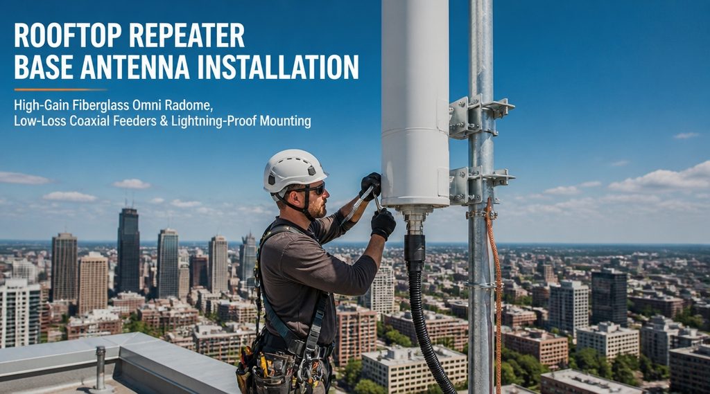
Most buyers treat gain as the headline number. It is really a budget line, and the budget has a legal ceiling.
Repeater antenna gain buys signal in one direction and takes it away from another. It never adds power.
This guide covers the four-line link budget, the gain figure worth ordering, the feeder, the lightning work, the aiming and the annual check.
The gain you can actually use
Antenna gain is not amplification. It is direction: the same energy concentrated into a smaller angle.
Where gain comes from
A vertical collinear antenna stacks radiating elements. Each added element concentrates the pattern in the vertical plane.
So the gain figure and the vertical beamwidth move together. Double the gain in decibels and the beam narrows by roughly the same amount.
Nothing in that process adds transmitter power. The aperture simply stops radiating energy upwards and downwards.
dBd, dBi and the 2.15 dB gap
Two reference points are in common use. dBd compares the antenna with a half-wave dipole; dBi compares it with an isotropic source.
The isotropic source does not exist, and it is 2.15 dB weaker than a dipole. So the same antenna reads 2.15 dB higher in dBi.
A catalogue that mixes the two units is not lying, but the comparison is invalid. Convert before you compare, and note which unit the licence uses.
The ERP ceiling
Regulators license effective radiated power, not antenna gain. Adding gain without reducing power raises ERP.
47 CFR 90.205 sets maximum ERP against antenna height and service radius. In the 450-470 MHz band, a station with an 8 km service radius is authorised up to 100 W ERP.
At 13 km the table shows 2 500 W, with a note that 500 W applies where the edge signal may fall below 39 dBu. The 150-174 MHz table gives 28 W at 8 km and 178 W at 13 km.
The height rule matters just as much. Above the reference height, allowed ERP falls with the square of the ratio: double the HAAT and the allowance drops by 6 dB.
That is the sentence to read before ordering a high-gain antenna. Raising the mast can cost you the very gain you just bought.
The four-line link budget
Four lines decide whether the site works. Only one of them is the antenna.
Line one: transmitter power
Take the repeater’s rated output and convert it to dBm or dBW. A doubling of power is +3 dB, and that is the only place real power enters.
Line two: feeder and connectors
Every metre of coax costs loss, and every connector adds a little. Use the cable datasheet figure at your own frequency.
Loss is additive in dB, so the arithmetic is simple: datasheet loss per 100 m, multiplied by your run length.
Line three: antenna gain
Add the gain in the direction that matters. For a collinear on a mast, that is the horizon, not the sky.
Gain in dBd keeps the arithmetic aligned with the licence. Gain in dBi needs the 2.15 dB correction first.
Line four: the working margin
Subtract the total loss from power plus gain, and compare the result with what the handhelds need at the edge.
A portable has no gain and a short antenna. The site is designed for the portable, not for the mobile with a roof mount.
| Line | Example figure | Running total |
|---|---|---|
| Repeater output | +40 dBm | +40 dBm |
| Feeder, 40 m at the datasheet figure | minus 2 dB | +38 dBm |
| Connectors and jumper | minus 1 dB | +37 dBm |
| Antenna gain | plus 9 dBd | +46 dBm ERP |
The example numbers are illustrative. Substitute your own datasheet values before you sign the order.
Choosing the gain figure
The right gain is the one that fills the service area without wasting signal above it.
Start from the service area
Draw the area you must cover, then find the worst case: the furthest point at the lowest terrain.
That point sets the required field strength. Everything else in the budget is arithmetic from there.
Vertical beamwidth and the near field
High gain narrows the vertical beam. On flat ground that is good, because energy goes where the users are.
On a hill above a town, the narrow beam can pass over the near streets entirely. The users directly below the site lose signal as gain rises.
This is why a 12 dB antenna sometimes covers a town worse than a 6 dB one. The pattern, not the number, decides.
Downtilt is part of the choice
A high-gain antenna usually needs electrical or mechanical downtilt to put the beam on the coverage area.
Downtilt reduces the effective horizon gain. Budget the tilted gain, not the catalogue peak.
If the tilt exceeds a few degrees, the peak gain figure is close to fiction for your site.
When lower gain wins
- The site is on a hill directly above the users.
- The service area is small and close.
- The feeder run is long, so loss already ate the budget.
- The licence caps ERP near the power you already run.
In all four cases, spending the money on height or on lower-loss feeder beats spending it on gain.
Reading a datasheet honestly
Three figures decide the purchase: gain, vertical beamwidth and the frequency range the gain applies to.
A repeater antenna gain figure quoted without a frequency is a marketing number. Gain varies across the band.
Ask for the pattern chart as well. It shows where the nulls are, and nulls matter more than the peak.
Feeder and connectors
Feeder loss is the quietest way to waste a good antenna. It is also the easiest line to measure.
Loss is per metre and per connector
Cable datasheets give attenuation in dB per 100 m at stated frequencies. Pick the row nearest your operating frequency.
Loss rises with frequency, so a cable that is fine at VHF can be poor at UHF. Read the right column.
Add the connector and jumper losses. Two connectors and a short jumper are small, but they are not zero.
Cable size against tower load
Thicker cable has lower loss and more weight. A long run of large coax loads the mast and the tower fixings.
Check the wind load figure the mast is rated for. Adding a heavy feeder and a large antenna can exceed it.
On a very long run, a remote-mounted repeater often beats a bigger cable. Shorten the coax instead of upgrading it.
Connector count discipline
Every joint is a place for water and a place for loss. Count them on the drawing before you climb.
Use one continuous run from the antenna to the equipment, with an entry bulkhead where the cable enters the building.
Label both ends. A feeder that cannot be identified is a feeder that gets replaced by guesswork.
Weatherproofing
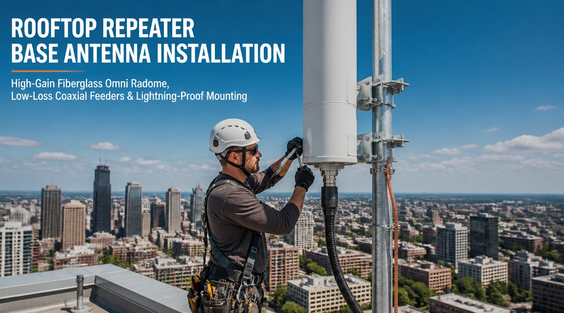
Water enters through the connector, not through the jacket. Tape and seal the joint, and do it before the antenna goes up.
Wrap with self-amalgamating tape first, then a weatherproof layer. A loose tail of tape is what fails first in wind.
Leave a drip loop below the connector so water runs off rather than into the joint.
Measure before you climb
Sweep the assembled feeder and antenna on the ground, before it goes up. Finding a bad connector at height costs a second climb.
Record that sweep. It becomes the reference that tells you whether the repeater antenna gain changed after the weather.

Mounting and lightning protection
This is the part that protects people and equipment, and the part most often skipped on small sites.
Stay inside the protected volume
IEC 62305-3 describes external lightning protection and life safety. The protected volume is defined by the air termination system.
An antenna clamped to the side of a mast is often outside that volume, even though it looks sheltered.
Move it into the protected volume, or extend the air termination so the antenna sits inside. Height is not protection.
Bond the feeder at entry
IEC 62305-4 covers electronic systems inside the structure. Its principle is equipotential bonding, not isolation.
Bond the coax screen to the building earthing system where it enters. Then the surge has a short path to earth.
Keep the separation distance from other metallic services. A long parallel run to a power conduit couples surge into the radio room.
Select the surge protector by type
The IEC 61643 series defines surge protective devices. Type 1 is for the point where the line enters and a direct strike current is possible.
Type 2 sits downstream for induced surges. Use a signal-line protector matched to the coax connector and the frequency range.
Confirm the protector’s frequency range covers your band. A protector rated for a lower band will add loss and reflect power.
Mast, earth and hardware
Bond the mast to the earthing system, not just to the coax. A mast that is un bonded becomes the path.
Use hardware that suits the environment: stainless where salt or humidity is present, and the specified torque on clamps.
Document the earthing arrangement. A future contractor will otherwise add a second, conflicting bond.
Azimuth and downtilt
Aim with data, not with a compass held at arm’s length.
True north, not compass north
A magnetic compass points at magnetic north, which differs from true north by the local declination.
That difference can be several degrees. Apply it before you record the bearing, or the site is aimed wrong from day one.
Record the bearing in true degrees on the as-built sheet, with the antenna model and the tilt setting.
Path profile first
Before climbing, check the terrain between the site and the coverage area. Ridges and buildings decide more than a few degrees of aim.
Pick three test points: near, mid and far. Note what obstructs each one and at what distance.
If the far test point is blocked by a ridge, no amount of repeater antenna gain fixes it. Move the site or add a second one.
Setting downtilt
Downtilt puts the beam on the users. It is set from the site height and the distance to the coverage edge.
Mechanical tilt is measured on the antenna bracket. Electrical tilt is built into the antenna and specified by the vendor.
Set it, record it, and check it after the mast work. A clamp that slipped changes the coverage without any alarm.
Verify in the field
Walk the three test points with a handheld and log the signal at each. Compare against the predicted values.
If the near point is weak and the far point is strong, the beam is above the users. Add tilt.
If the far point is weak and the near point is strong, the beam is too low or the path is obstructed.
Commissioning record
Commissioning produces numbers. Without them, every later fault is a debate.
Take a return loss baseline
Sweep the feeder and antenna together and save the trace. That sweep is the reference for every future check.
Measure at the equipment end, with the jumper included. The reading then matches what you will measure next year.
Save the file with the site name and date. A photograph of the screen is better than nothing, and worse than a file.
Walk the coverage
Test at the three points used for the path profile, plus two points inside the building if the site serves one.
Log signal, location and the radio used. The radio matters, because a different model changes the reading.
Compare with the prediction. A large gap means the repeater antenna gain is not reaching the ground where you expected.
Photograph what matters
Photograph the antenna, the bracket, the tilt setting, the connector sealing and the earth bond.
Next year, the photograph is how you know whether the clamp moved or the tape was always like that.
Periodic inspection
An outdoor antenna degrades slowly and then fails suddenly. The inspection schedule is what catches the slow part.
Interval
IEC 62305-3 treats inspection and maintenance as separate activities, with the interval depending on the risk and the environment.
Coastal, industrial and high-wind sites need shorter intervals than a sheltered inland mast. Set yours from the conditions, not from habit.
Record the interval in the site file and keep to it. An inspection that moves with the budget is not a schedule.
Visual checks
- Antenna orientation and tilt against the as-built sheet.
- Clamp torque and any sign of movement on the mast.
- Cable ties, hangers and the drip loop.
- Connector tape, cracking and water staining.
- Earth bond and mast fixings, including corrosion.
Electrical checks
Repeat the return loss sweep and compare with the baseline. A shift means water, a loose connector or a damaged antenna.
Check the earth continuity from the mast to the earthing point. Measure, do not assume.
Confirm the surge protector is the type and model recorded at commissioning, and that its indicator is normal.
Replacement criteria
Replace the antenna when the sweep shows damage that cannot be traced to a connector, or when the pattern has clearly changed.
Replace the feeder when loss has risen beyond what the link budget can absorb. There is no point re-aiming a bad cable.
Replace hardware that is corroded beyond its rated strength. A clamp is cheaper than a fall.
Common mistakes
- Ordering gain by the catalogue number instead of the ERP budget.
- Comparing a dBd figure with a dBi figure.
- Ignoring downtilt when quoting the gain.
- Putting a large antenna on a mast rated for a small one.
- Mounting outside the protected volume.
- Bonding the coax but not the mast.
- Aiming by compass without declination.
- Commissioning without a saved sweep.
Each of these is a project risk, not a detail. Two of them can also void an insurance claim.
Frequently asked questions
Is higher repeater antenna gain always better?
No. Gain narrows the vertical pattern, and a narrow pattern can miss users close to the site.
It also raises ERP, which the licence caps. Higher gain is a trade, not an upgrade.
How much gain do I need for a 10 km radius?
Start from the required field strength at the edge, then subtract feeder loss and add the gain that closes the gap.
The answer depends on height, terrain and the handset. Any figure quoted without those three is a guess.
Can I use a higher-gain antenna to avoid a taller mast?
Sometimes, on flat terrain with a clear path. Gain cannot bend around a ridge.
Check the path profile before you substitute gain for height. Terrain usually wins.
How often should the antenna be inspected?
At least once a year on a normal inland site, and more often where salt, ice or industrial fallout is present.
After any severe storm, inspect before restoring service. The sweep will tell you more than the eye.
Does gain help the receive path too?
Yes. An antenna is reciprocal: the same pattern that concentrates transmit energy also collects more on receive.
That is why a repeater antenna gain change alters talk-in as well as talk-out, and why handset range improves both ways.
Does a surge protector add loss?
Yes, a small amount, and it belongs in the budget. Check the datasheet figure and include it with the connectors.
A protector outside your band adds more loss and can reflect power back. Match it to the frequency range.
What if the sweep is fine but coverage is poor?
Then the problem is pattern, height or obstruction, not the cable. Review the tilt and the path profile.
Repeater antenna gain only helps where the beam actually lands.
Where to start
Draw the service area, find the worst point, and calculate the budget in four lines. That order prevents most bad purchases.
Then check the licence ceiling, choose the gain and the tilt together, and only then choose the antenna.
Finally, record the commissioning numbers. They are the only way to know, next year, whether anything changed.
Contact us
Send us the site coordinates, the service radius and the repeater output. We will work the budget with you.
Contact our sales manager directly.
Sales Manager: Kevin
WhatsApp: +852 60731163
WeChat: +8616623617128
Email: fengfanannie@163.com